


29 May LC Net Plus Manual 2.11.13
How Can We Help?
1 Preface
1.1 Software application background
Thank you for using LC Net Plus software.
LC Net Plus (asynchronous display version) is intended for the control system of LED asynchronous display and its main functions are:
- Editing and creating programs for CT series LED screen control systems.
- Program related operations: program definition, setting program window layout, program editing, program sending, program preview and adjustment, etc.
- Setting function: automatic tasks, time and communication port settings, etc.
1.2 File description
This LC Net SoftwareV6.11 manual describes how to control and manage a CT gray-scale LED screen with LC Net Plus software.
2 Introduction to CT control system
2.1 System configuration
The CT control system consists of:
A. The main control board: directly controls the program display and management of the LED display screen.
B. LC Net Plus software is the supporting software for the CT control system. LC Net Plus connects with the main control panel, typically through the computer network or COM port.
C. Other supporting accessories: directly connected to the main control panel and perform special functions, for example: brightness sensor, temperature probe, humidity probe, etc.
2.2 System communication
CT system communication connection ports include RS232/RS485 serial port, TCP/IP network port, or USB flash disk port, etc.
- Serial port mode
RS232:With RS232 mode, the computer COM port connects to the main control panel directly. LC Net Plus simultaneously manages and controls one LED display through one computer serial port.
RS485:With RS485 mode, the computer COM port connects to the main control panel through the RS232 RS485 converter. The main control panel can be linked using a RS485 cable; which will allow LC Net Plus to simultaneously manage and control up to 255 LED displays through one computer serial port. - TCP/IP network mode
The computer can remotely manage the display screen through LAN (Local Area Network) or Internet, via wire or wireless mode (such as WIFI). - USB flash disk mode
Save your message to a USB flash disk, when the disk is plugged into the controllers USB interface, the program data will be imported into the controller automatically.
Other communication modes: - GPRS/CDMA mode
Wireless GPRS/CDMA mode: The computer can remotely manage the display screen through mobile phone network by connecting GPRS or CDMA communication DTU. - Other wireless mode
The computer can remotely manage the display screen through a public wireless band by connecting wireless module (for example: RF module, Bluetooth or ZigBee Module).
3 Brief introduction and basic settings
3.1 Software Characteristics
Main features of LC Net Plus V6.11:
- Supports CT series control systems.
CT 5200 supports RGB full color, 256 gray degree scale.
CT 4200 supports RGB color, large size, no-gray scale.
CT 3200, CT2200, CT1200 supports RG dual colors, no-gray scale. - Supports multi-communication modes such as network, serial port, USB flash disk and more.
- With clear and simple interfaces, users can easily make, play and control programs.
- Software menu is easy to use allowing fast, easy message entry and edits.
- With hierarchical management of programs in each menu type to provides a clear structure for convenient maintenance.
- With multi-program modes, multiple programs can be stored.
- Up to 10 windows can simultaneously play different action modes; each window can be enhanced with a flashing surround to highlight the window.
- CT control systems supports various program types such as video, animation, photographs, Word/Excel, clock, text, etc.
- Supports text program which can be edited in several languages, any font and any size.
- Text program can be set to be transparent or hollowed-out, and overlay a picture, animation or video program.
- Supports temperature display (temperature sensor must be installed externally).
- RTC management and settings of Real-Time Clock, to display analogue or digital world clock. Time counter (count up or down).
- In networking mode, up to 256 LED screens can be networked and managed.
- Programs can be played according to a play schedule.
- Multiple adjustment modes such as manual, time or automatic adjustment (brightness sensor must be installed externally).
3.2 Software running environment
3.2.1 Computer Compatibility
- OS: Windows2000, Windows XP, Windows Vista, Windows 7 (32 or 64 bit).
3.2.2 External running environment
LC Net Plus is the supporting software for your LED display control system.
The communication connection modes are: serial port, network port, etc., plus the USB controller version can transfer program data by USB flash disk.
3.3 Software installation and uninstall
3.3.1 LC Net Plus
Run “LC Net Plus_V6.1.exe” located on the install CD, simply follow the prompts.
To uninstall, run “Start” – “All programs” – “LC Net Plus 6.1” – “uninstall LC Net Plus”.
3.3.2 Video decoder
To display videos, first install video decoder on the computer. Run install files found on install CD.
3.4 Software Installation and Set-up
3.4.1 Software installation
Run “Start” – “All programs” – “LC Net Plus V6.1” – “LC Net Plus”; or double-click “LC Net Plus” shortcut icon on the desktop.
Figure1 Software language
3.4.2 Define LED screen (searching controllers; set screen parameters)
The software setting is “Define LED screen” is one of the first steps in setting up your software.
Set-up Steps:
1) Click “Setting” – “Define LED screen”, as shown in Figure2.
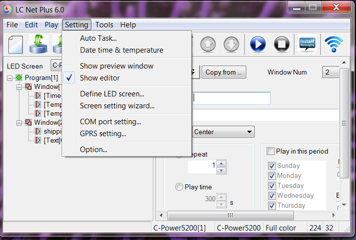
Figure2 Go to “Define LED screen”
2) In the LED screen list dialog box (Figure3), click “New” to establish or click “Edit” to change the screen parameters.
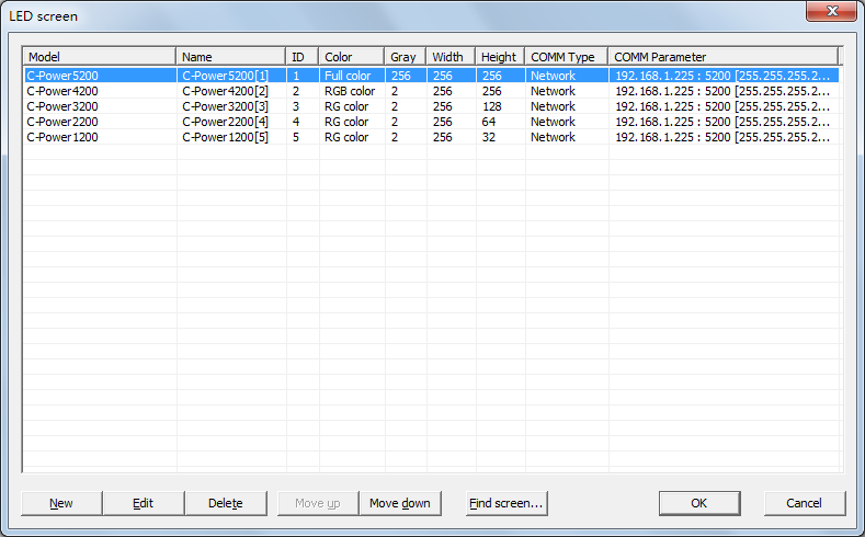
Figure3 LED screen list
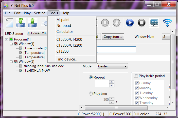
3) If the controller is connected to the computer (COM port or network port), click “Find screen” (or click “Tools”- “Find device” on the menu), the “search device” dialog box will pop up, to search the devices connected the computer.
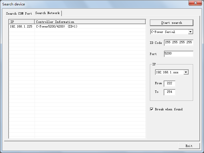
Figure4 Search device
4) After clicking the “New” or “Edit” button, enter the password in the authority confirmation box, and the “Screen editor” a box will pop up, as shown in Figure5 and Figure6.
5) In the “Screen editor” dialog box define LED screen according to the hardware setting condition of the screen controller.
A. Model: select the correct controller type on the left side of the dialog box.
B. Name: the user can choose a name for LED screen. The name will appear at the edit field. If no name is entered, the system will automatically display “CT 5200 (ID)”
C. ID: it is used to distinguish between two or more LED screens. If there is only one screen, use the default value “1”.
D. Color: select the color of the LED screen: e.g. Full color.
E. Width and Height: actual pixels of the LED screen.
F. Font library: click![]() button to set the font library type, once the controller is connected, the font libraries will automatically be detected.
button to set the font library type, once the controller is connected, the font libraries will automatically be detected.
G. Communication type: select COM port mode, network mode, or GPRS/CDMA mode.
COM port mode: RS232 or RS485 mode
Set the original port of PC COM port1 communication, and then Baud rate.
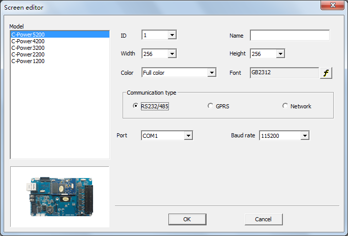
Figure5 “Screen editor” dialog box under COM port mode
- Network mode
Additional setting items3 after connecting the network port with the control panel.
a. IP address: the IP address of the control panel
Local area network: Once connected to a local area network (default gateway 192.168.1.1) user can directly change the IP address by using Tools – shown below).
The Password for changing the configuration is: 26888.
Internet: if the control panel is connected by internet, the user should input the IP address of the internet gateway.
b. ID code: is the IP package ID code of the control panel (such as password).
ID code should be the same as the control panel setting so it can be recognized and controlled by the LED control panel.
c. Port: network port (5200)
Local area network: input network port of the control panel.
Internet: input network port of the control panel. Also, identify the network port to computer and control panel through the gateway setting port in the computer control panel.
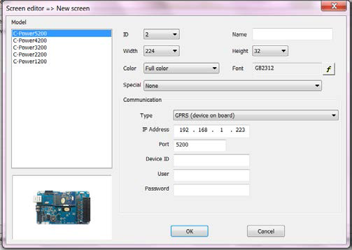
Figure6 “Screen editor” dialog box under network mode
- GPRS mode
Both GPRS and CDMA modes are sending signals through the wireless network by connecting GPRS or CDMA DTU. For details, please refer to relevant documents.
6) After the LED screen definition is complete, LC Net Plus is ready to set up a message for each screen, and the mapping between panel and software is complete.
-
After the LED screen definition is complete, backup the file “screen.cfg” which is automatically created under the installation directory of LC Net Plus. If software or a new computer is installed, the backup can be used to restore the “Define LED screen” settings.
4 Program Editing
4.1 Software overview
During the normal running of software, the interface is shown as Figure7, consists of two parts: console and program preview windows
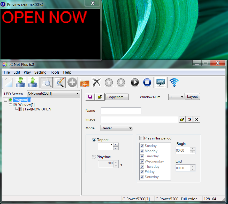
Figure7 Software interface
4.1.1 Preview window
Preview window is an important part of LC Net Plus software. It simulates the same display effect as the actual LED screen and will provide a “what you see is what you get” program editing interface.
- Program overall preview: user can see overall display effect through preview window after program editing is completed. Please refer to section 4.3.4.
- Window: user can adjust the size and position of each window using the preview window. Please refer to section 4.3.2.
- Play item preview: user can preview the actual play effect through preview window as each play item is edited.
For additional settings of preview window, please refer to section 5.1.
4.1.2 Console
Console is an operating platform for program editing, setting and sending messages. The console is shown as Figure8 and Figure9, which consists of main menu, tool bar and program edit zone.
- Main menu and tool bar: For the button functions of the tool bar, please refer to section 6.1.
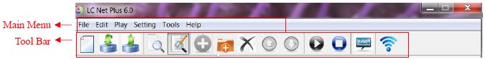
Figure8 Main menu and tool bar
- Program edit zone consists of “Message” and “Attribute box”. After message item is selected, the attribute box shows the attribute item choices.
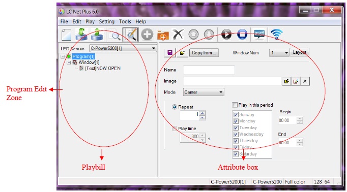
Figure9 Program edit zone
4.2 Message
When the LED screen definition in section 3.4.2 is complete, LC Net Plus can then create a message for each LED screen. The message zone which is located at the left side of the program edit zone in Figure9 shows the list if complete messages ready to be displayed.
- Each message consists of one or more program(s).
- The various messages display screens are as shown in Figure10.
- The messages for each LED screen will be stored automatically. In addition, with “Import” and “Export” functions, you can backup and recover the current message.
For advanced operations of the message commands, please refer to section 5.2.
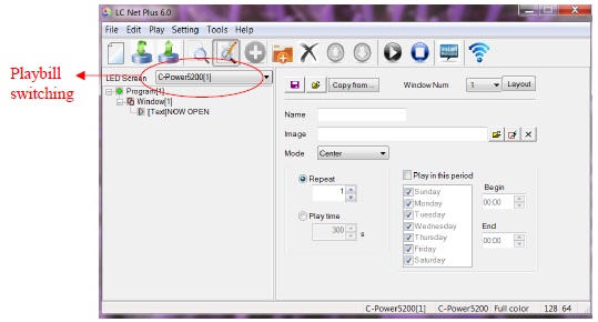
Figure10 Switching message display screens
4.3 Program
Program is the display content of the LED screen. It consists of the window layout, various play items and more.
- Each message consists of one or more program(s). If permitted by the program data size, the CT control system can store up to 512 programs. The window layout and content of each program in each message may be different.
As shown in Figure11, a complete program consists of the following three parts:
1. Program
- The CT series control card can store up to 512 different programs.
- In message, the programs are played from the top to bottom.
- User can set the play schedule and play time of the program.
For additional program management information, please refer to section 4.3.1.
2. Window
- Each program can be divided into 10 windows.
- The contents of each window, in each program, are absolutely independent and played simultaneously.
- The position and size of the window can be adjusted, and sometimes overlapped. When more windows are overlapped, the content of the smaller window number will be covered by the bigger one.
For additional details about the window command, please refer to section 4.3.2.
3. Play Item
- User can set several play items within one window.
- The play items in each window are played from the top to the bottom.
- Types of play item: text type, clock type, environmental data type and external document type.
For details additional details about the play item command, please refer to section 4.3.3.
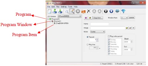
Figure11 Levels of message
4.3.1 Management of program
1. Program management
Method 1: select a program from the message (at the left side of the console); click “Add”, “Delete”, “Move up”, “Move down” under the “Edit” on the Toolbar.
Method 2: click the relevant tool button in Tool Bar, as section 6.1 shows.
Method 3 (recommended): right click a program in the message (located at the left side of the console); select the shortcut from the pull down menu, as shown in Figure12.
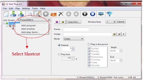
Figure12 Shortcut management of program
2. Program setting
In Figure13, when one program is selected in the message at the left side of the console, the attribute box at the right side will show its attribute. The following items can be set:
A. Name: self-define program name.
B. Background and mode: select background picture and layout in the current program to display; the background picture cannot be completely covered by the program windows
C. Program play control: when displaying more than one program, they are played according to program number from the top to the bottom. The user can set the repeat times or play time of each program. If only one program is played, it will be played repeatedly without restriction.
D. Schedule time(s) for message to play: You can choose to have messages run for specific time periods.
E. To set time selection:
- When start time entered equals to end time the program is played all the day: for example, the start time is “00:00” and the end time “00:00”.
- When the start time is less than the end time: for example, the start time is “8:00” and end time “20:00”, the program is played during “8:00~20:00”.
- When the start time is greater than end time: for example, the start time is “20:00” and the end time “8:00”, the program is played during “20:00 ~ 23:59” and “0:00 ~8:00”.
- Note: if all programs are set to “play restricted by time period” and no content is appointed in some period, the LED display screen will be blank/black.
F. Initial setting of window
Copy: click “Copy” to access the “Copy program window”. User can select and copy the existed program, as shown in Figure14.
Number of window(s): select the number of window(s) for the current program.
Layout: click “Layout” button to select the division type of window for the current program.
- For details about window management and settings, please refer to section 4.3.2.
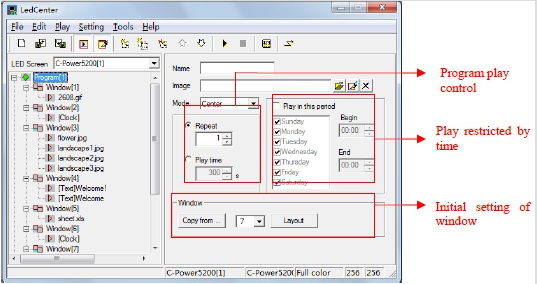
Figure13 Program attributes
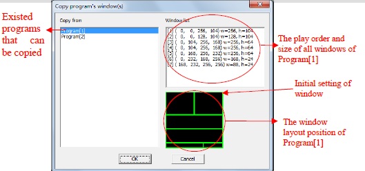
Figure14 Program window layout
4.3.2 Manage window- placing multiple messages in segments on one window.
In each program, the program display screen can be divided into as many as 10 independent windows. Windows can differ from each other in size and position.
1. Management of window
Method 1: in program setting, user can set the number and layout of the window, or directly copy the existed program. Please refer to section 4.3.1 and Figure14.
Method 2: select a window item from the message (at the left side of the console); click “Add”, “Delete”, “Move up”, “Move down” under “Edit” in Menu Bar.
Method 3: click the relevant tool button in Tool Bar, as section 6.1 shows.
Method 4 (recommended): right click a program or a window in message (at the left side of the console); select right shortcut in the pull down menu, as shown in Figure15.
When using the overlap feature in the program, the position of each window can be overlapped. In this case the content of the window with the smaller number will be covered by the bigger one.
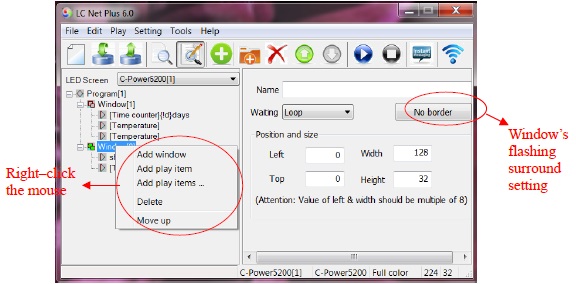
Figure15Window management
2. Setting of window
When the window is selected, the attribute box at the left side will show its attribute, see Figure15. The following items can be set:
A. Name: self-define the name of the window.
B. Flashing surround: click the flashing surround setting (see Figure15), the “Border selector” pops up, as Figure16 shown. Select the surround type. Every window can set the flashing surround to highlight the window’s content.
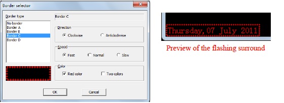
Figure16 Flashing surround setting
C. Waiting: if all program items in the current window have not finished playing, while the program items in other window have not yet finished playing, the user can change the waiting time of the current window.
D. Position and size: input the position and size of the window.
Multiple messages in one window: when a “Program” or “Window” is selected in the message, the mapping position of each windows in the current program will appear in the preview window. The frame of current window is bright yellow while the others are green, as shown in Figure17. The position and size of each window can be adjusted by dragging the mouse in the black block on the frame
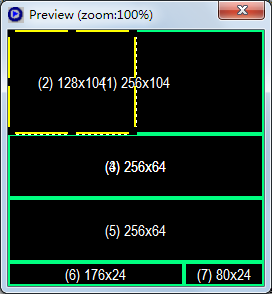
Figure17 Editing size and position of the preview window
4.3.3 Management and editing of play item
1. Management of play item
Each window can hold any number of play items; every play item is played in sequence from the top to the bottom. The play item is managed in following ways:
Method 1: select one play item in the message at the left side of the console; click “Add”, “Delete”, “Move up” or “Move down” using “Edit” in Menu Bar.
Method 2: click the relevant tool button in Tool Bar, as section 6.1 shows.
Method 3 (recommended): right click a play item in the message (at the left side of the console); select a shortcut from the pull down menu, as shown in Figure18
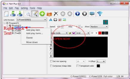
Figure18Management of play item
Click “Add play items”, add more than one document, as shown in Figure19.
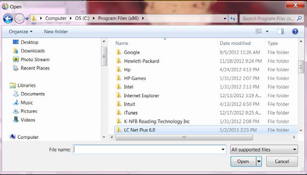
Figure19Add play items
2. Editing of play item
The content of each play item can be selected by clicking the “Play item type” button as shown in Figure20. The types are listed below:
- Text type: In text mode the fonts available are limited; however using IMAGE mode allows access to the complete font library on the users computer.
- Clock type: simulative clock, digital clock, etc.
- Environmental data type: temperature (Celsius or Fahrenheit) or humidity.
- External document type: video, animation, graphic document, text document, etc.
The following sections provide information about each type of editing of the play item.
4.3.3.1 Text type (More than 60 effects, transparent overlap or hollow-out effect)
At the left side of the message, select the play item to be edited. If text button is clicked, the play item is text. Please see Figure20 and Figure21.
There are two modes of text type: “image mode” and “text mode”.
There are more than 60 effects in the text program, including: snow fall, mosaic, slide zebra, fan open, etc. User can click the preview window to preview and select effects, as Figure22 shown.
1. Image mode
As shown in Figure20, computer fonts are converted in the content / edit zone to picture format. LC Net Plus supports text program of any languages, fonts and sizes.
- Text input: Input the text content in the input field. Or paste the text content with office file format information from clipboard. Or click
 and
and  buttons above the input field to open TXT or RTF files, or save the text in input field to files.
 - Text setting: Every character can be set or modified one by one. The fonts, size, text color, background color, bold (B), italic (I) and underline (U), etc.
- Effect setting: To set the effect of each message; “speed” and “stay” time, click the effect pull-down menu to select or click the preview icon to virtual preview and select the text effect, as Figure22 shown. When select the “random” (the preview icon is “?”, the controller will play the text program in random effects.
- Typesetting: Click the typesetting buttons on the left side of the text input field, to set the text align left, center, or right.
- Set row spacing: To set row spacing, and Y-offset, it can adjust the text height and exact position, even by screen pixel.
- Compress image data: When this option is selected, the text program data in Image mode will be compressed to reduce the time for transmission and save the memory space on the controller.
- Transparent or hollow-out: Text program can set to be transparent or hollowed-out, and overlay on a picture, animation or video program, as shown in Figure23 and Figure24.
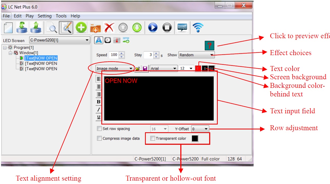
Figure20Text program (image mode) edit interface
2. Text mode
As shown in Figure21, display the font library available on the main control card.
- Text input: Input the text content in the input field. Click and buttons above the text input field to open TXT or RTF files or save the text in the input field
- Text setting: Every character can be set or modified individually. The size, text color, and reverse color ().
- Effect select: The message “speed” and “stay” time can be set by using the effect pull-down menu. From here the user can click the preview icon to preview and select the text effect, as Figure22 shown. When select the “random” (the preview icon is “?”, the controller will play the text program in random effects.
- Typesetting: Click the typesetting buttons on the left side of the text input field, to set the text align left, center, or right; and align up, Y-center, or down.
- Set row spacing: Select “line spacing”, to set the distance between two lines
- Transparent or hollow-out: Text program can be set to transparent or hollow-out, and overlay a picture, animation or video program, as Figure23 and Figure24 shown.
Figure21 Text program (text mode) edit interface
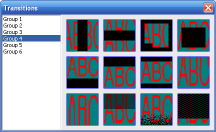
Figure22 Effect preview and select
3. Text transparent or hollow-out
Text program can be set to overlay a picture, animation or video program’s window, as Figure23 or Figure24 shown. Use the following settings:
1) The window of text which you want to overlapped other window.
2) The text window’s number is bigger.
3) Select “Transparent” option.
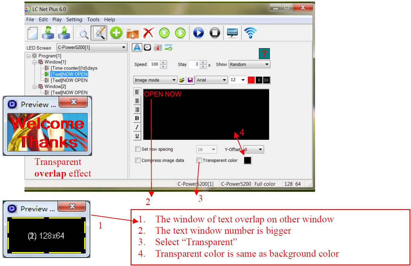
Figure23 Text transparent overlap setting
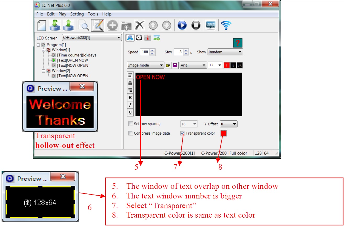
Figure24 Text transparent hollow-out setting
4.3.3.2 Clock type (Analogue or digital clock, count up/down)
In the message at the left side of the program edit zone, select the play item to be edited. If the “clock” button is clicked, the type of the play item is clock. Clock type program include: “Clock”, “Time counter” and “work counter’.
1. Clock
A. Caption: add a message before clock, also choose size and color. The program is displayed instantly.
B. Clock option: select clock display items, display on line or not; selection of data and clock format: several formats are available.
C. Show hands and marks: There are two options for displaying the analogue clock.
D. Time zone: select the time zone, the clock program will display the local time1 of the selected time zone.
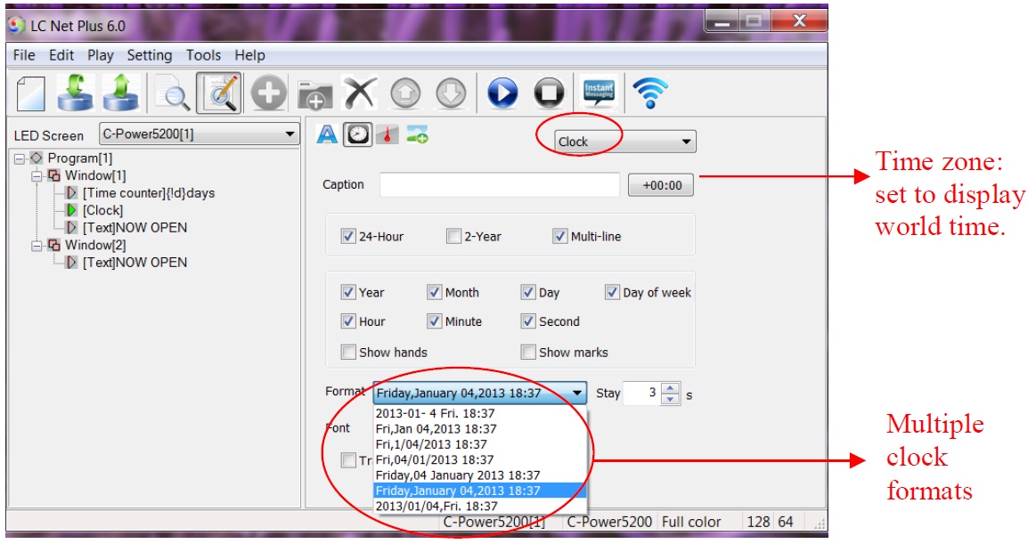
Figure25Clock program edit interface
- Time adjust: Clock type program will use the real time chips on the controllers to automatically run and display the time, to adjust the time, please see the section 4.4.2
- Clock transparent display: as shown in Figure26. User needs to follow these 3 steps to achieve the transparent display effect.
1. The clock window must be overlapped in front of the window to be used for background.
2. The window number of clock should be bigger than the one to be covered.
3. Select “Transparent”.

Figure26 To set up transparent clock display
2. Time counter
A. Content: Select the contents to be displayed, by clicking the variable tag text listed below the content input field. The controller will calculate the exact time, variable and value to be display. For example, click {!d}Days, the controller will calculate and display the exact number of days between the current time and the Base date and Base time, as shown in Figure27 and Figure28.
B. Type: Count up or counter down.
C. Base date and Base time: When “count up” has been chosen, the base date and time should be earlier than the current time; when “count down” has been chosen, the base date and time should be later than the current time.
D. Transparent: The same as the clock program, the counter can be set to transparent and overlap on other window. Refer to Figure26.
E. Font setting: Font size and color can be chosen.
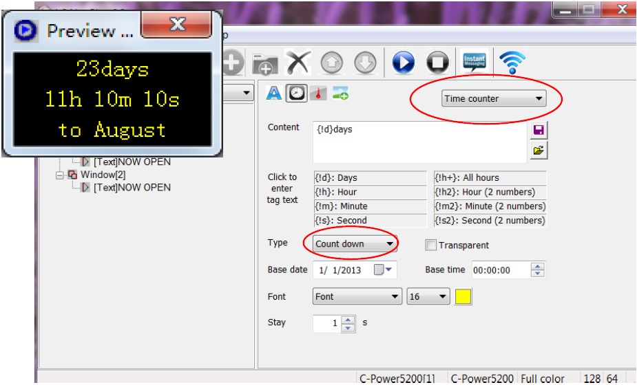
Figure27 Count down setting
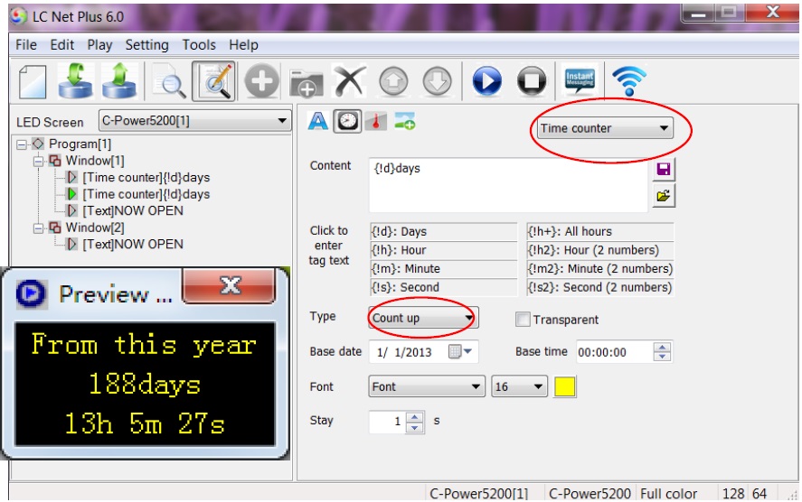
Figure28 Count up setting
3. Count Down Process
A. Content: Calculate automatically. Set the count type “Count hours” or “Count days”.
B. Base date and start time: Base date and the count start time (at o’clock sharp).
C. Hours of day and calculated days: Select the work day which should be counted during a week, and set how many hours should be calculated in the work day(8,12,16 or 24 hours).
D. Font setting: Font size and color can be chosen.
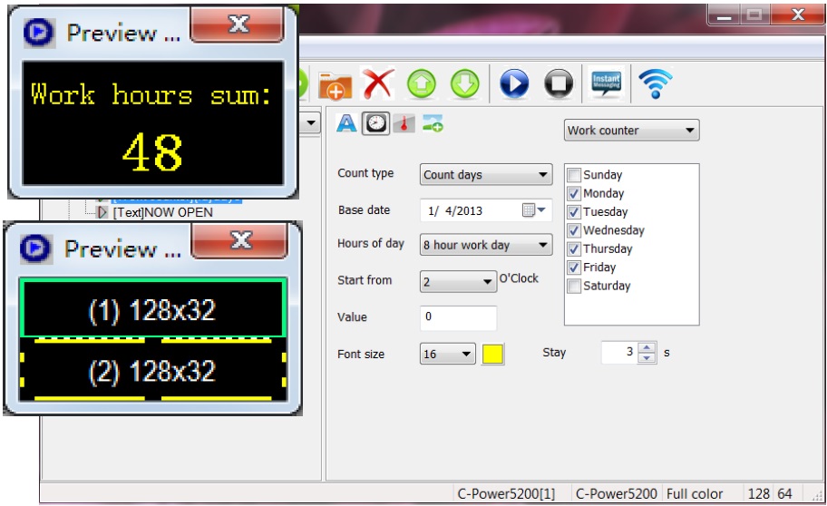
Figure29 Work counter setting
4.3.3.3 Environment data type1 (temperature program, humidity program)
In the message at the left side of the program edit zone, select the play item to be edited. If “Sensor” button![]() is clicked, the type of the play item is environment data type. Please see Figure30.
is clicked, the type of the play item is environment data type. Please see Figure30.
A. Caption: User can add a message before temperature information, and set the stay time and color of the characters. This type of programming is displayed instantly.
B. Temperature program: The controller must be connected to an external temperature sensor. Select “Temperature”, choose the unit type: “Celsius” or “Fahrenheit”.
- Temperature adjustment: Depending on the placement of the probe on the display, the actual temperature and the temperature display maybe different. Use the temperature adjusted function to modify the value, please see section 4.4.2.
C. Humidity program: The controller must be connected to an external humidity sensor.
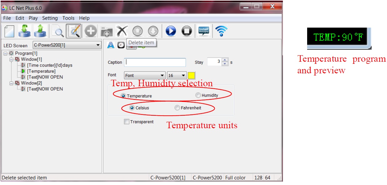
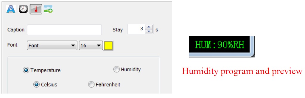
Figure30 Temperature, humidity program edit
4.3.3.4 External document type (text, office file, image, animation, flash, video)
In the message at the left side of the program edit zone, select the play item to be edited. If “Document” button is clicked, an “Open file” dialog box pops up. Please see Figure31.
CT control panel supports the following document types:
- “Text files”(*.txt)
- “Office document”(*.doc , *.xls, *.rtf)
- “Image file”(*.jpg, *.bmp, *.gif, *.png, *.tif)
- “Animation or video1 file”(*.gif, *.avi, *.swf)
More than 60 effects for text, office document and image file; such as: snow fall, mosaic, slide zebra, fan open, etc. User can click the preview window to preview and select effects, as Figure22 shown.
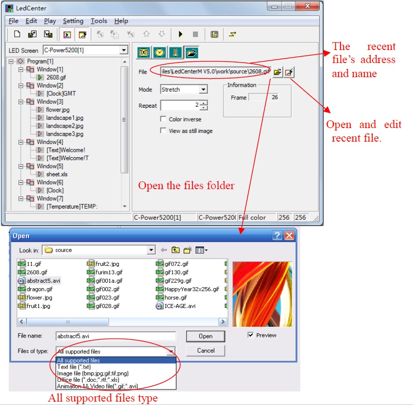
Figure31Open file window
1. Text file and Office document
When using a Word (*.doc), Excel (*.xls), Text-only format (*.txt) or Rich text format (*.rtf), the attribute box of the relevant documents will appear at the right side of the program editing zone, as shown in Figure32.
- Effect selection: Message motion “speed” and “stay” time can be chosen. Click the effect pull-down menu to select or click the preview icon to preview and select the text effect, as Figure22 shown. When selecting “random” (the preview icon is “?”, the controller will play the text program in random effects.
a. Word file (*.doc): View as text: text will be recomposed automatically to comply with the size of the window; Color inverse: background color and text color will be reversed.
b. Rich text format (*.rtf): Color inverse: background color and text color will be reversed.
c. Excel file (*.xls): Color inverse: background color, text color and sheet frame color will be reversed.
d. Text-only format (*.txt): to set text color.
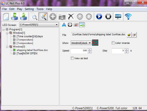
Figure32 Effect setting of Office file
2. Video file
As shown in Figure33, if a video file (*.avi) is selected, video image processing “Mode”, “Repeat” times can be set.
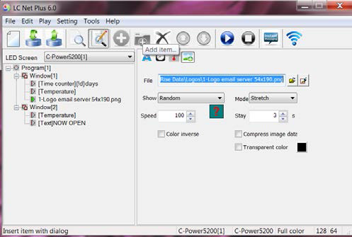
Figure33 Effect setting of video file
3. Animation file
As shown in Figure34, if a flash (*.swf) or GIF animation file is selected, animation may be played. Picture processing “Mode”, “Repeat” times of animation play and the setting of “Color inverse” can be selected. GIF files can also be selected to be displayed as static picture (view as still image).

Figure34 Effect setting of animation file
4. Picture file As shown in Figure35, if JPG, BMP, PNG, TIF files are selected or GIF files are displayed as static pictures (that is: viewed as a still image).
- Effect: Moving “speed” and “stay” time can be chosen. Click the effect pull-down menu to select or click the preview icon to virtual preview and select the text effect, as Figure22 shown. When selecting the “random” (the preview icon is “?”, the controller will play the text program in random effects.
- Compress image data: Reduces data size and time of transmission; the picture quality may be slightly reduced.
- Transparent: Transparent display refers to when one or more window overlaps. Refer to the text transparent setting, see section 4.3.3.1.
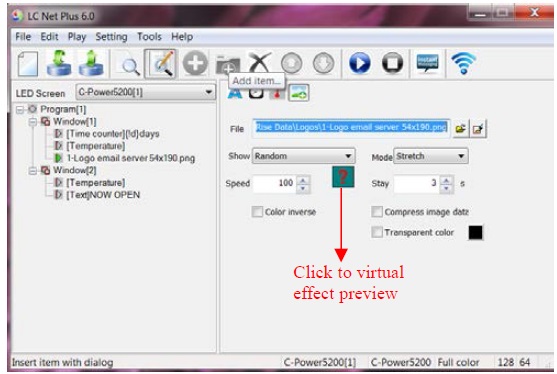
Figure35 Effect setting of picture file
4.3.4 Program preview
After program each is complete, it can be viewed in the preview window:
1) Click “Play” – “preview” in menu bar or button in the tool bar. In the preview window, the effect of this display screen can be shown.
2) Click “Play” – “Stop” or press button in the tool bar, stop preview.
4.3.5 Program data sending (network, serial port, USB flash disk)
After the program edit and preview confirmation are complet, send the message to the main control panel of the screen:
1) Click “Play” – “Send program data…” in main menu; or click button in tool bar, and the box “Send data to LED screen” pops up. The choices are:
- Send to current: send program data to the current panel.
- Send the selected: send the program data of the selected panel at the left side “LED screen list”.
- Send One to Multi: send the current program data to more than one screen.
- Send to USB disk1: send the current panel’s program data to the USB flash disk; transfer the data via USB disk.
- Format screen: if an error occurs, it can’t be saved, refresh the card’s program data, format the screen and resend the data.
- Show data screen: read the cards and show the program files in screen.
2) When the computer is connected to the controller, click “Send to current” or “Send to the selected”, the computer will send the data via the network or serial cable, as shown in Figure36 and Figure37.
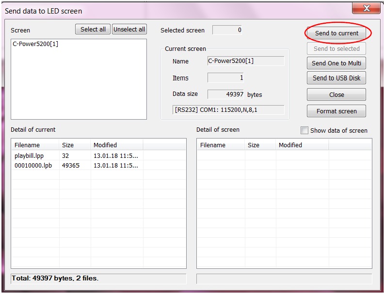
Figure36Dialog box of sending data
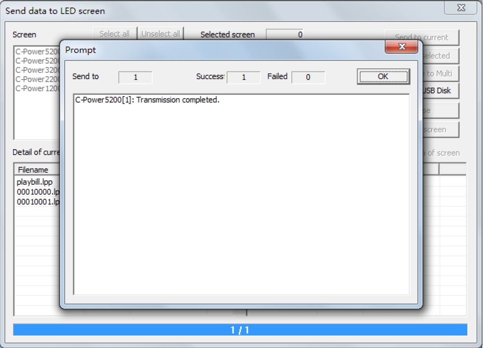
Figure37Data sending completed
3) When transferring program data via USB flash disk (the controller should be a USB version), the USB flash disk can plug into the computer’s USB interface, and then click “Send to USB disk” button, as Figure38 shown. Select the USB disk’s driver, then click send button. The files include control files and program data files, as Error! Reference source not found.
Note: Insert the USB flash disk into the controller USB interface, the controller will read the data automatically. Don’t modify the USB disk data before using.
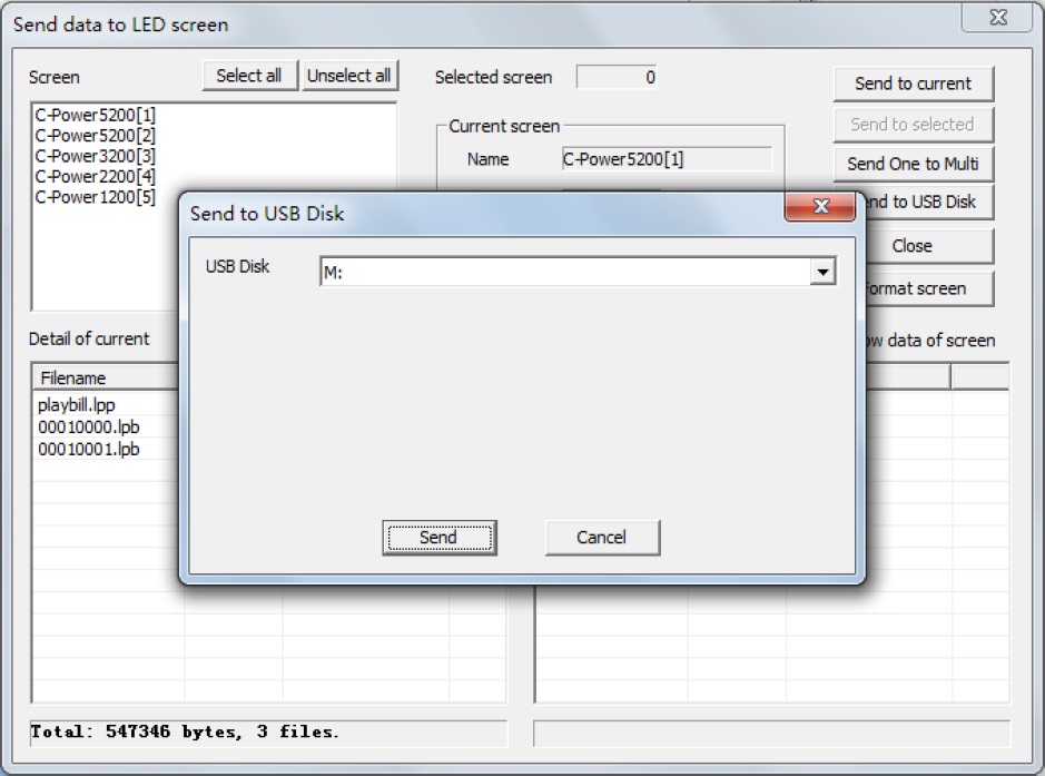
Figure38 Sending program data to USB flash disk
4.4 Play management
4.4.1 Playing schedule
The programs can be set to play at the specified date and specified days of week.
Steps:
1) Click “Edit” – “playing schedule” in menu, as shown in Figure40.
- When there are no other messages scheduled to play, or the scheduled messages do not cover the entire time period, to avoid a black screen, the “Undefined time play all programs” selection needs to be the selected default.
- The controller will play the selected programs as scheduled.
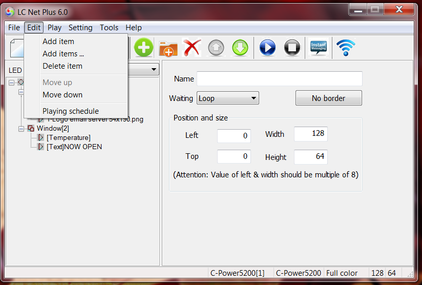
Figure39 Message playing schedule
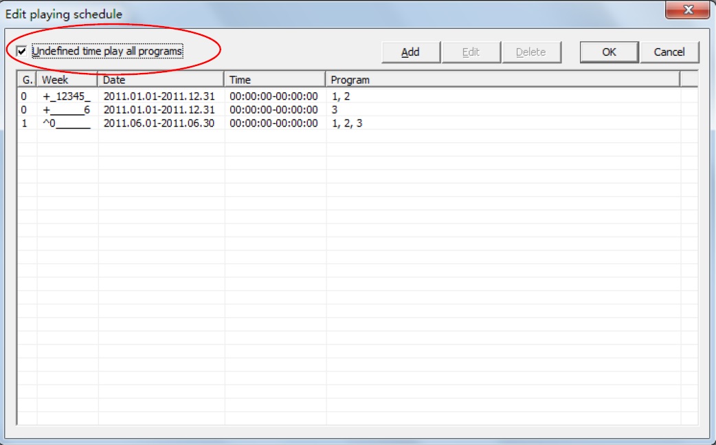
Figure40 Playing schedule list
2) Click “Add” button, or select an old schedule and click “Edit” button, the “Play schedule item” dialog box pops up, as Figure41 shown.
- Item grade: Every schedule item has a grade, when two or more schedule items conflict; the item which has higher grade will be executed first.
- Relationship of date and day of week: The playing schedule can be set according to the date or the day of week, or their association:
AND: Playing at the special date AND the special day of week, when both the date and day of week requirements have be met.
OR: Playing at the special date OR the special day of week, when one of the date or day of week requirements has be met. - Time:
a. Start time equals to end time: for example, the start time is “00:00” and the end time “00:00”, the program is played all the day.
b. Start time is less than the end time: for example, the start time is “8:00” and end time “20:00”, the program is played during “8:00~20:00”
c. Start time is greater than end time: for example, the start time is “20:00” and the end time “8:00”, the program is played during “20:00 ~ 23:59” and “0:00 ~8:00”.
3) The playing schedule will be sent to the controller with the program data sending (sector 4.3.5).
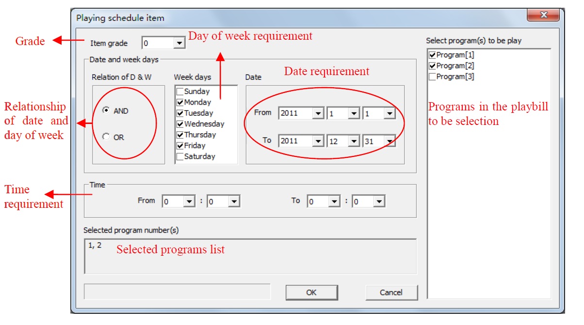
Figure41 Edit a playing schedule
4.4.2 Setting and inquiry for screen time and temperature (read and adjust)
Function description: set or calibrate the time of real time clock of current screen.
Steps:
1) Click “Setting” – “Date time & temperature” in menu.
2) Select the screen (from the list on the right) which is connected with the computer. Hold Ctrl key and click the screen list, user can select multiple screens.
3) Time set and read: as Figure42 shown.
Input time manually or adjust according to the current computer time, and then click “Set to screen”.
Click date and time “Read from screen” button, read back controller’s current real time.
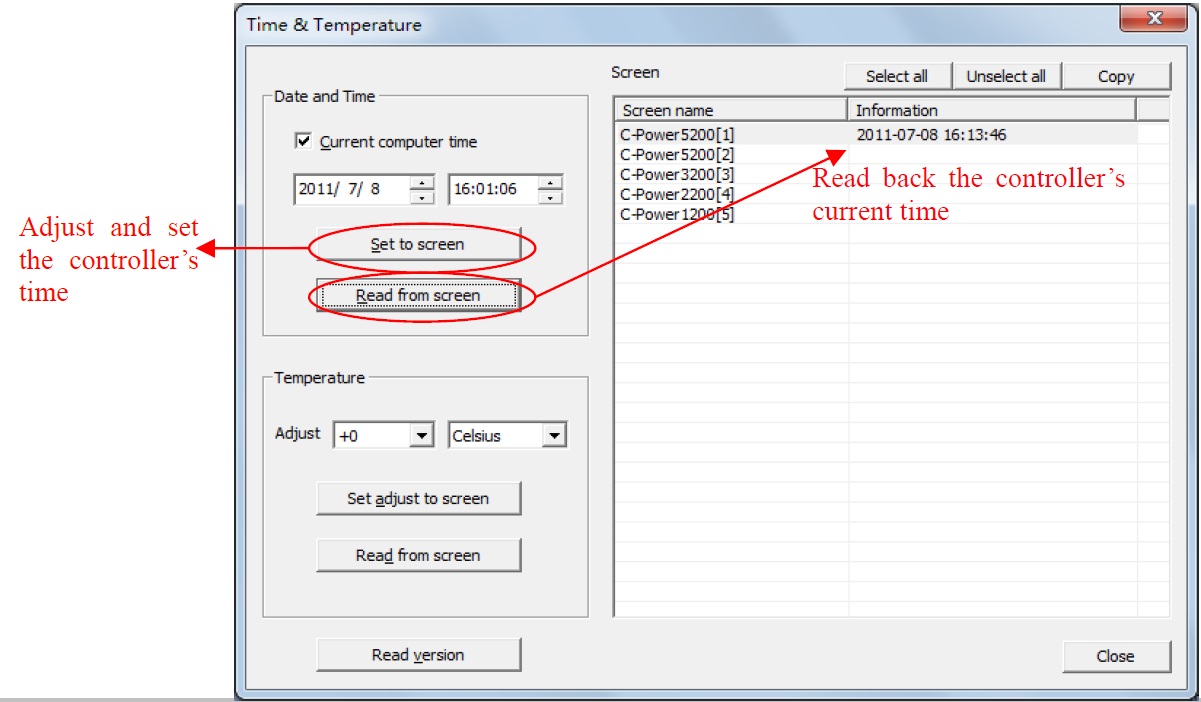
Figure42 Time setting
4) Temperature adjusted and read: the controller will detect and display the environmental temperature when a temperature sensor is installed. The actual temperature may be different than what is displayed in the temperature program due to the placement of the sensor on the display. To adjust, use the temperature function to modify the value. Click temperature’s read from screen button to read the temperature value which detected by temperature sensor.
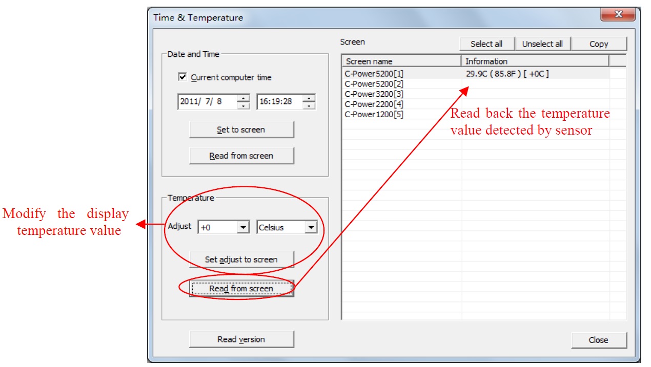
Figure43 Adjust and read temperature
5) To verify controller version: Click “Read version” button to view the controller information.
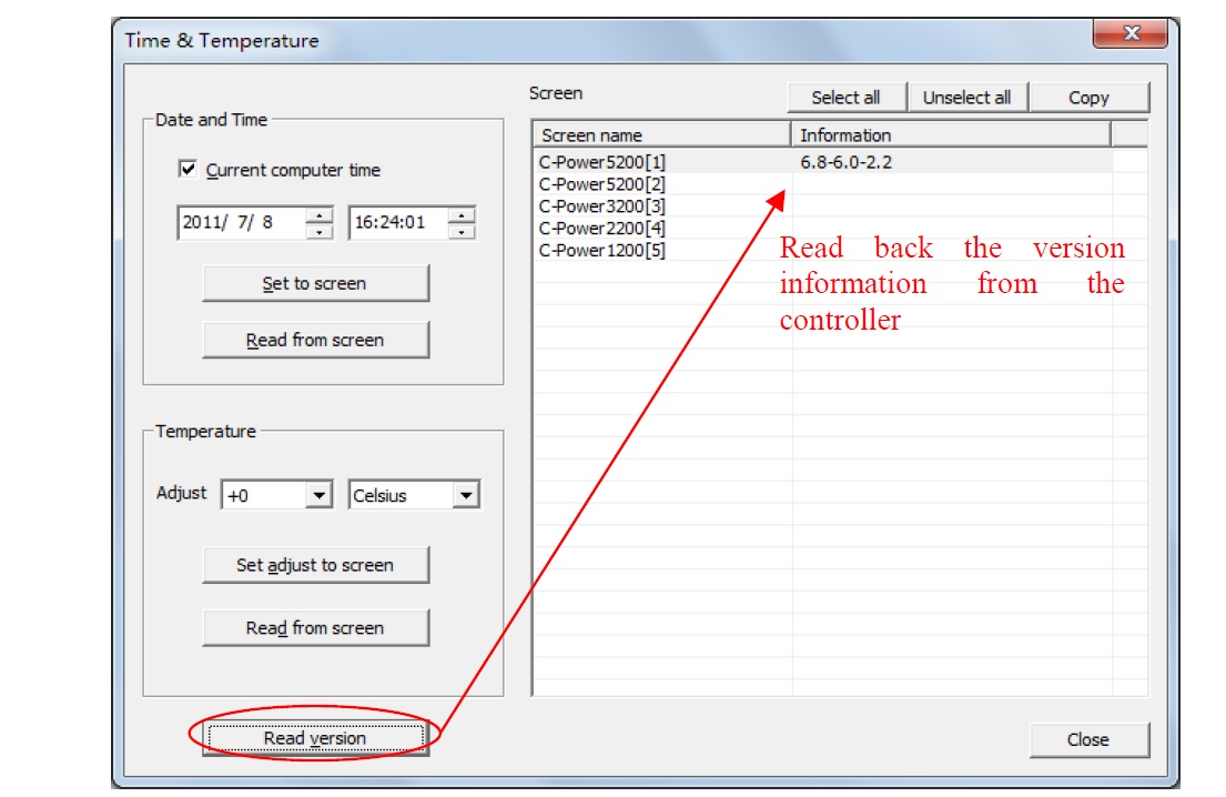
Figure44 Inquiry controller’s version information
4.4.3 Setting and Adjusting Auto turn on/off, brightness setting
Function description: set automatic on/off; set screen brightness.
Steps:
1) Click “Setting” – “Auto task” in menu. The dialog box of “Auto ask manager” pops up, as shown in Error! Reference source not found..
2) Power on/Power off: to set the ON/OFF time of the screen; during “ON-OFF” time period, the screen is turned on, while during “OFF-ON” time period, the screen is turned off.
3) Brightness: (Requires brightness Sensor)
- Drag the rulers, set the time or some period time’s brightness
- Click and select the appoint time period (hour), and then drag the ruler on the right side to set the appoint brightness. The 24 hour’s list can browse the brightness setting.
Brightness setting range from “0” to “31”:32 is a fixed brightness setting.
Set to “-1”: The screen adjusts the brightness automatically, but the controller must connect brightness sensor, the controller adjust the screen’s brightness based on the environmental brightness detected by the sensor.
4) After setting is complete, select the target screen and click “Set to screen”.
5) Before or after sending, click “Read from screen” button to search the setting condition of the current auto task of the main control panel.
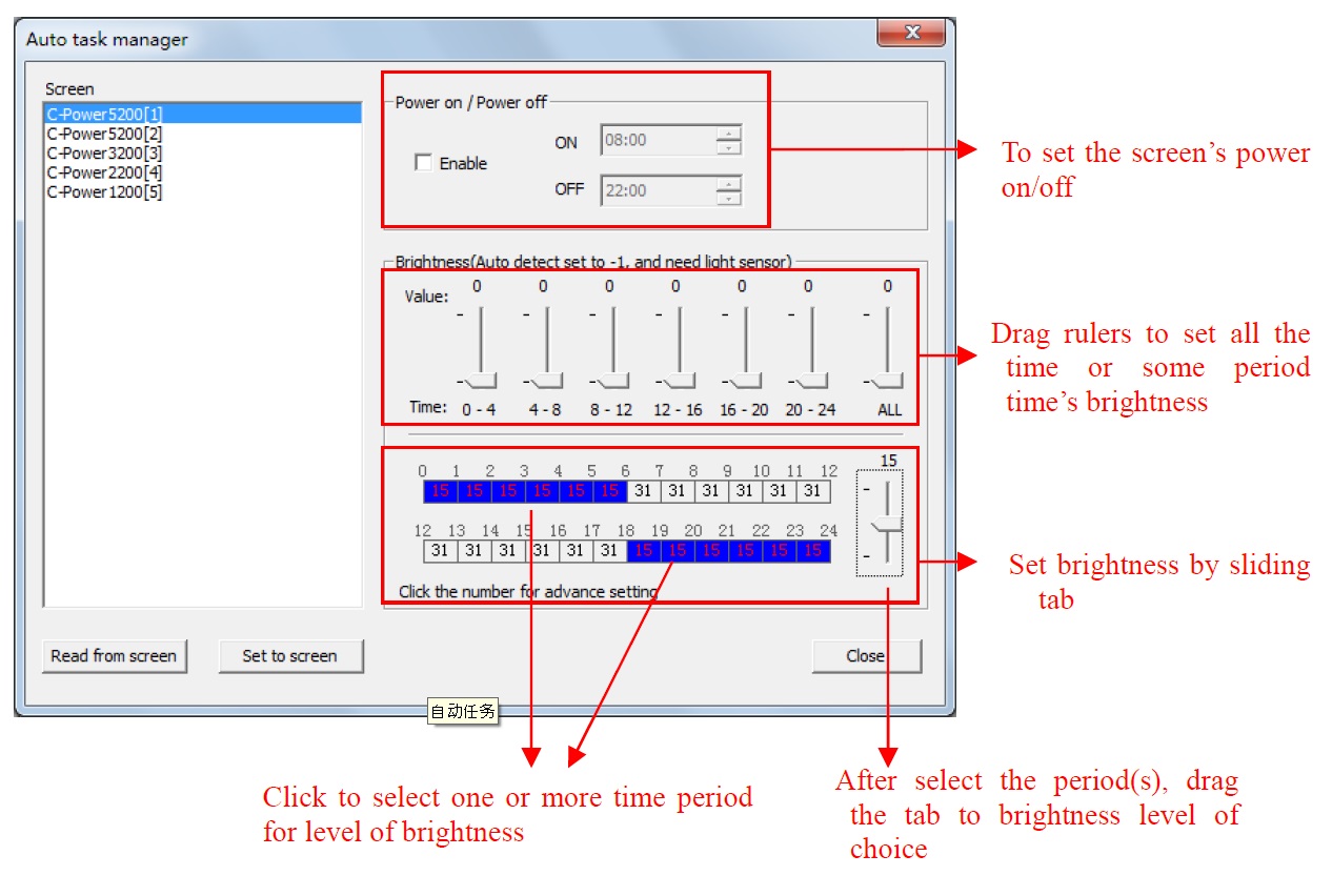
Figure45Automatic setting modes
5 Other functions
5.1 Software option (preview window location, default setting)
Select “Setting” – “Option”, the user can set the preview display window parameters as shown in Figure46.
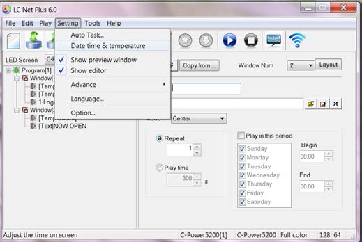
Figure46Go to “Option” dialog box
“View” page Main window view:
“Minimize window to system tray bar”: when this setting is selected, the software window is minimized to system tray bar by clicking![]() .
.
 Figure47Minimize window to system tray bar
Preview window view: Click![]() to display.
to display.
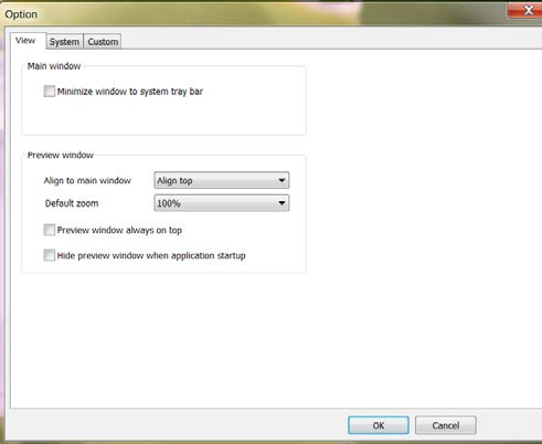
Figure48Option dialog box
- Tip: right click the preview window to see the display size (100%, 200%, 300%,400%). The preview window can be zoomed in or out.
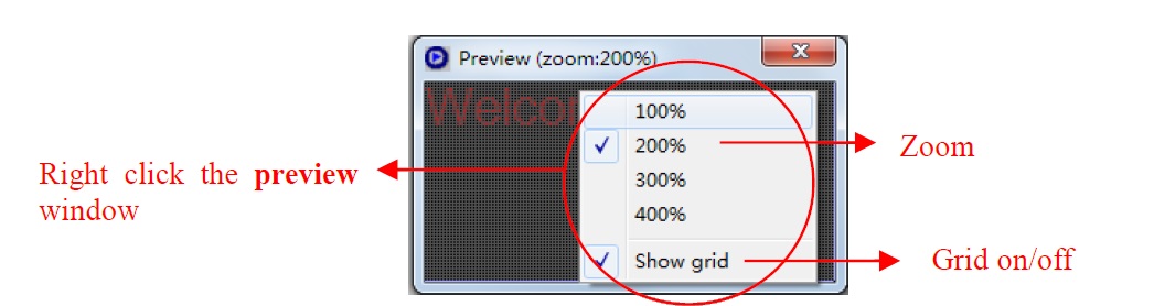
Figure49 Preview window setting(right click)
1. “System” page: to set the shut down time of Windows system.
2. “Custom” page: to set the default text program type, clock program format etc.
Figure50
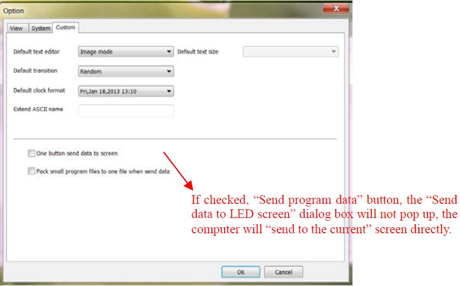
Figure50
5.2 Message Import and Export
After LED screen definition is completed (see section 3.4.2), LC Net Plus will set up program data for each screen and save them automatically.
5.2.1 Build new message
Target: Clear the old message of current screen and create new one.
Method and step: click “File” – “New” in menu bar, or click in tool bar.
5.2.2 Export program data
Target: export the program data to current screen (*.lpl).
Follow these steps:
1) Click “File” – “Export” in menu bar, or click in tool bar.
2) Select export position in the dialog box “Export to message” (as shown in Figure51) and enter the export file name. Click “Save”. The message file of current panel will be stored to the file.
Figure51 Importing message
5.2.3 Import program data
Target: import the program data once all edits are complete.
Follow these steps:
1) Click “File” – “Import” in menu bar, or click in tool bar.
2) In the dialog box “Import message” (as shown in Figure52), select the program file (*.lpl) to be imported. The “Information” at right side of the dialog box shows the screen parameters of the program file. Confirm the imported program consistent with the parameters of current screen.
3) Import to multiple screens: if select the option “To multiple screens” as shown in Figure52, a dialog box “Import to multiple screens” as shown in Figure53 pops up after a file is selected. Hold Ctrl key and click the screen list, user can select multiple screens, and then import the program file to multiple screens.
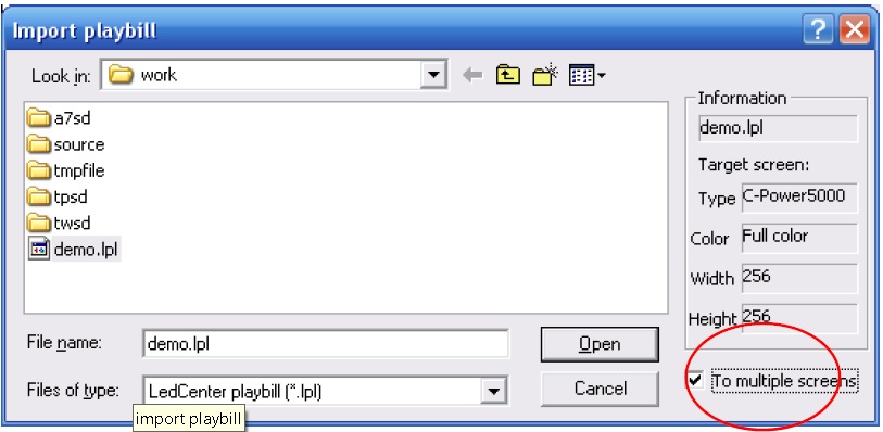
Figure52 Import message
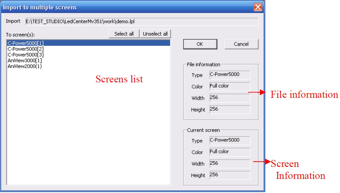
Figure53 Import to multiple screens
6 Appendices
6.1 Button function of tool bar
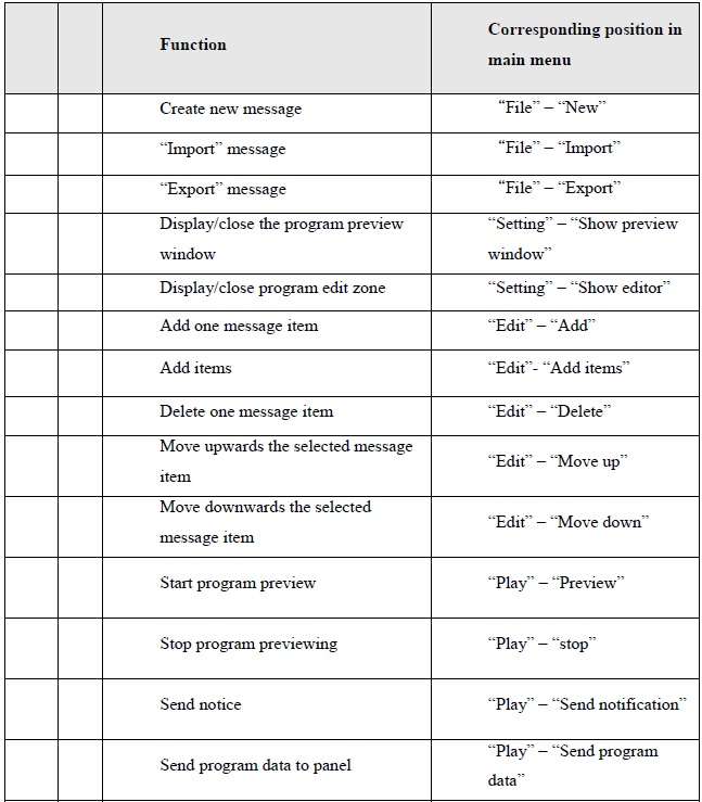
Table1 Button list of console tool bar
6.2 Trouble shooting and warning dealing
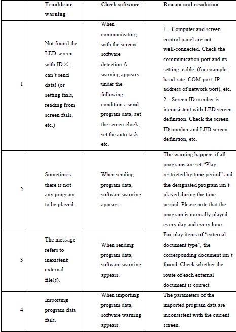
Table 2 Quick search for trouble shooting and warning dealing