


04 Oct 7.1.2.2 Versa Net Config – LED Display Configuration
How Can We Help?
LED Display Configuration
According to the quantity of scan board, there’re two different modes for LED display configuration: No scan board cascaded mode or cascading scan board mode.
1) No scan board cascaded mode (one PSD100 Asynchronous card only) Switch to “Screen Config” page in Fig. 7-1, the interface of a No scan board cascaded mode is shown below in Fig. 7-12:
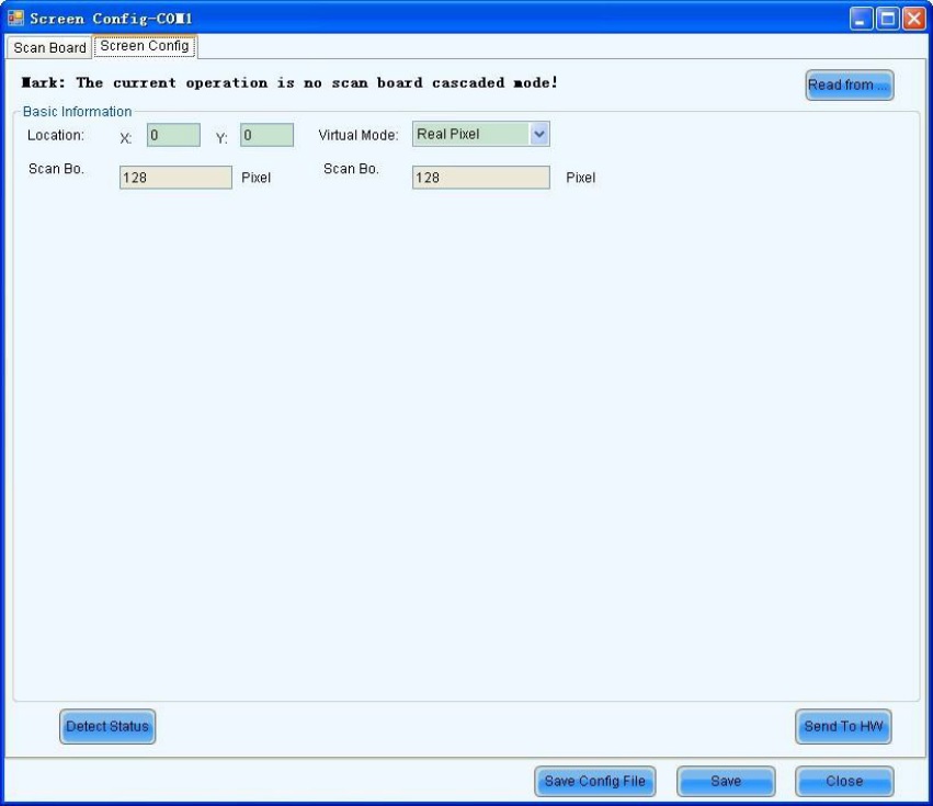
Fig. 7-12 Screen config in No scan board cascaded mode
Read form HW
This is used for the application to read the LED display configuration information from the hardware.
2) Cascading scan board mode (PSD100 Asynchronous card cascading MRV300/MRV320 scan board)
The mode of the cascade receiving the card is divided into sending card mode and multi-display configuration. The former is asynchronous card without box carrier, equal to the sending card.
Multi-display configuration is usually used for dual panels. Both panels playing the same picture.
The multi-display mode does not support correction.
There are three LED display types: a simple screen, standard screen, and complex screen. These options will be shown at the top of each the Screen Configuration page. Choose a screen type before any configuration operation. Configurations for different types of screens will are as follows…
a) Simple Screen Configuration
Simple screen means each scan board drives the same pixel array, edit items below according to LED display status.
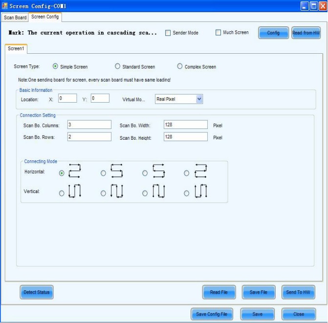
Fig. 7-13 simple screen configuration page
Sender Mode
If asynchronous card carries no box carrier, please tick this item
Multiple Screens
Tick this item to configure multiple panels
Read File
Used to load the LED display configuration settings from a file
Save File
To save the LED display configuration settings to a .scr file
Send to HW
To send LED display configuration settings to the connected PSD10 Asynchronous card
Save
Used to save the settings to a FLASH chip to ensure the data won’t be lost if the hardware is powered off.
Location
This designates the upper-left corner of a rectangular area of the computer display. The rectangle area of the computer display is called the mapping area. Content inside the mapping area will be shown on the LED display. The default location is (0,0), which is actually the upper-left corner of the computer display.
Virtual Mode
Specify the pixel mode of the LED display. The option could be a real pixel or virtual 3 LEDs or virtual 4 LEDs.
Scan Board Columns/Row
These are the number of columns and rows of the scan boards (receiving cards) array of the LED display.
Scan Board Width/Height
These two parameters in the Scan Board Info panel refer to the width and height of the pixel array driven by a scan board (receiving card). They must be set the same as those set in the Scan Board page.
b) Standard Screen Configuration
Configure scan boards connection routing manually, and each scan board could drive different pixel array.