


08 Jun 7.1.2 Versa Net Config – Start Manually
How Can We Help?
Start Manually
7.1.2.1 Smart Setting
Operating steps:
1) Select “Config Screen “option in the Screen Config window (Fig.7-1), and click ”Next”, enter screen config window.
2) Click “Smart Setting “button in “Scan Board “page and to open the Smart Setting dialog as shown below,
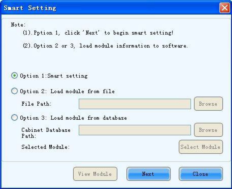
Fig. 7-4 Smart Setting dialog
3) Select “Option 1: Smart setting “and click “Next” to activate smart setting wizard. The Smart Setting Step 1 page will appear, as shown in Fig. 7-5,
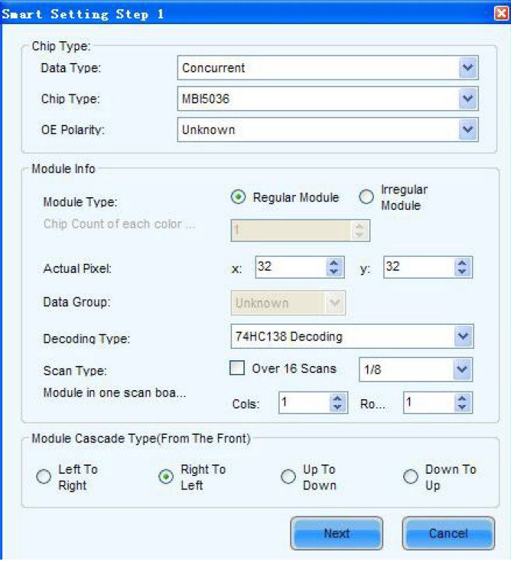
Fig. 7-5 Smart Setting Step 1
Data Type
Data type: Options have parallel drive, three-color 1-dot series, three-color 8-dot series, three-color 16-dot series, four-color 1-dot series, four-color 8-dot series, and four-color 16-dot series.
Chip Type: Select the drive chip type from the list according to what is actually used for the cabinets, e.g. MBI5036, MBI5042 etc.
OE Polarity: This option can be High Effective, Low Effective or Unknown.
Module type: The option can be regular module or irregular module. (Irregular module is not supported by this version)
Actual Pixel: This is the size of the real pixel array of a module. X represents the width and Y the height.
Decoding type: The options can be Static, 74HC138 Code or Straight Decoding, choose according the type LED display module actually used.
Scan Type: The options could be any scan rate between 1 scan and 1/16 scan or unknown. Rows and columns of the Module in one scan board (also named receiving card): This is the size of the module array in the cabinet which is being configured by smart setting.
Module Cascade Type: Select the corresponding option according to the module connection routing. Note the cabinet should be viewed from the front when considering the cascading direction.
1. If the module array size is set as the default (1 column, 1 row), the modules in the first rows of all cabinets will be lighted (LED lights on).
2. If the module array size is set as real numbers, the last module of each first row of the of all cabinets will be lighted (LED Lights on).
4) Click “Next” in“ Smart Setting Step 1”page to enter ”Smart Setting Step 2”page as shown in Fig.7-6. Select according to the module status,
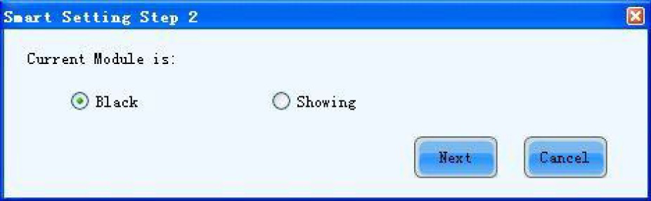
Fig. 7-6 Smart Setting Step 2
This step will be skipped if module OE polarity is known and set in Smart Setting Step 1.
5) Click “Next ” in “Smart Setting Step 2”page to enter ”Smart Setting Step 3” page as shown in Fig. 7-7,
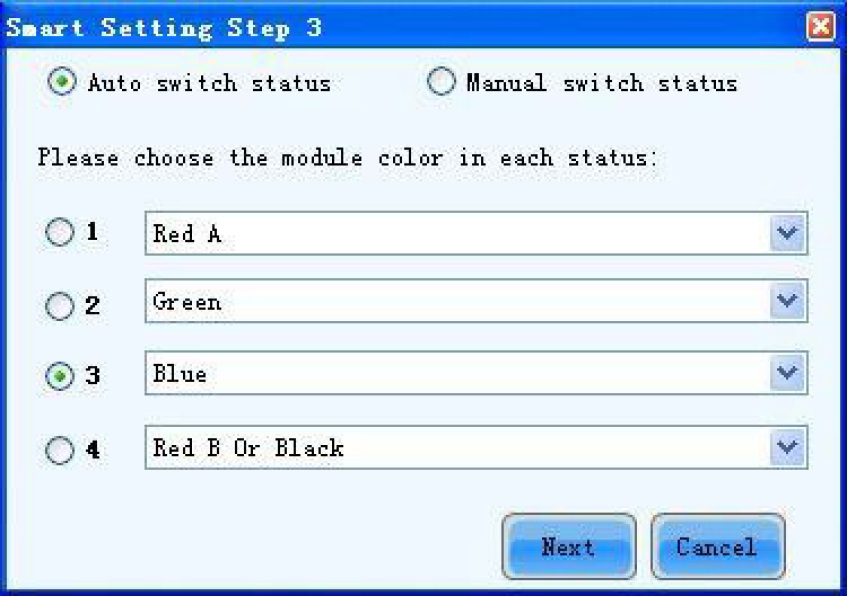
Fig. 7-7 Smart Setting Step 3
6) Click ”Next” in “Smart Setting Step 3”page after selection to enter ”Smart Setting Step 4”page as shown in Fig. 7- 8,Enter the number of LED rows that are lightened in a module.
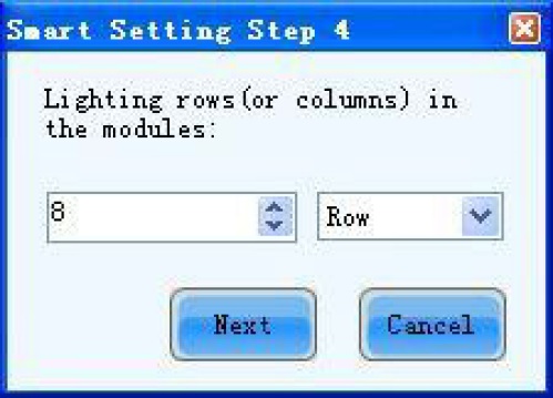
Fig. 7-8 Smart Setting Step 4
7) Click “Next” in ”Smart Setting Step 4“ page to enter “Smart Setting Step 5”page as shown in Fig. 7-9, Enter the number of LED columns that are lightened in a module.
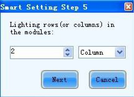
8) Click “Next” in “Smart Setting Step 5 to enter “Smart Setting Step 9”page as shown in Fig. 7-10, Click the corresponding grids according to the position of the lightened LEDs until there are no lighted LED. A line of the lightened LED routing will
be drawn at the same time. A message indicating the Smart Setting Step 9 has finished will appear when enough LED have been processed.
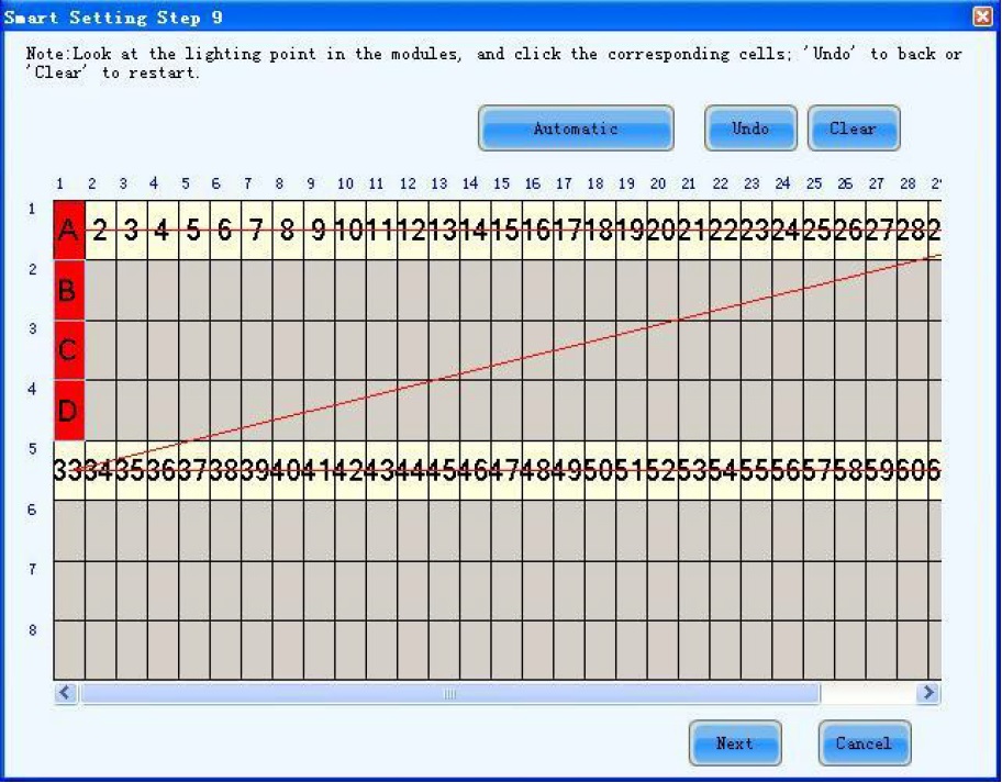
Fig. 7-10 Smart Setting Step 9
Press left button and drag the mouse to accomplish quick route drawing. Use “Automatic” button to display drawing route lines of the same pattern.
9) Click “Next” In “Smart Setting Step 9”page to open “Save Module” dialog and save the settings through all the smart setting steps. The “Save Module dialog” is shown in Fig. 7-11. Saving the module settings to files (module configuration files or cabinet database files) will make it easier to perform module configuration for another LED displays constructed by modules which require the same settings as the one just set. (Choose Option 2 or 3 in “Smart Setting dialog“(Fig.7-4) in Step 2), select corresponding files and modules and smart setting is done.) Click “Finish” to finish smart setting after saving. Just click “Finish” if you don’t want to save the settings.
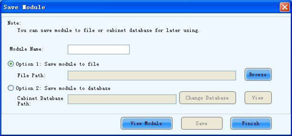
Fib. 7-11 Save Module dialog
The saved module settings can be used in Fig. 8-3 of Step 2) by choosing option 2 or 3 to simplify smart setting process.